Tuesday, March 26, 2019

3/18: The Final Dry Runs

This week, the team focused exclusively on full dry runs for both of our systems. We fully intend to finally fly operations next week, as the weather is improving. Thus, this week is effectively assurance that we are mission capable. To simulate the missions as much as possible, we started the simulation in the lab and proceeded to complete our simulations outside. This was done to simulate packing, per-operational considerations, and transportation. Essentially, we left nothing untested. To start the dry run, we performed the full pre-flight packing procedure and planning steps for both our flagship aircraft, the M600 and C-Astral Bramor (Figure 1). In lab, we also drew flight areas, discussed hypothetical missions, checked weather (which would have been out of limitations, so we modified them to be within limitations for the run), and other miscellaneous tasks that may be necessary for field missions.

Figure 1: Running through the packing checklists for both aircraft involved in the dry run.


Once outside, we assumed primary roles for the missions. Ryan led up the team focusing with the M600, and Kyle acted as the pilot for the C-astral. I worked as the equipment manager for the C-astral team. This was the final role at which I am yet to act as in a dry run, at it made sense for me to be a part of the C-astral team as this is the aircraft I am most likely to work with. Running through the checklist was effective. It is clear that the C-astral team is now very familiar with the system and works well as a team. No major issues appeared while performing the checklist steps and the aircraft was constructed without issue and in efficient time, as it would need to be in the field (Figure 2 and 3).

Figure 2: The aircraft fuselage mounted onto the catapult. An early step in constructing the aircraft pre-flight.


Figure 3: The fully constructed C-astral with armed to deploy parachute.

Being that it was raining lightly outside, this was also an opportunity to validate that the aircraft is at least moderately weather proofed (Figure 4). While setting up the aircraft in the rain made some of us nervous, it did build confidence that the aircraft will perform well in a realistic field environment. Being that Indiana has unpredictable weather in the Spring, it is entirely possible that light precipitation could begin during future operations.

Figure 4: The constructed C-astral fuselage and wing section with noticeable moisture from rain on the aircraft.

After the simulated C-astral mission was complete, Kyle and I spent time working through functions on the digital interface with Professor Hupy (Figure 5). predominately, the purpose of this interaction was to be reminded of key aspects of this aircraft's flight control, as well as learn pointers regarding potential mistakes that could be made. Ultimately, Kyle and I are likely to be the pilots throughout the season.

Figure 5: Learning more about the digital interface on the ground control station.
Ultimately, I think the crew is mission capable and ready for next week.


Tuesday, March 19, 2019

Week of 3/4/19: Improving C-Astral Setup Efficiency

This week, being likely the last week with poor weather, was critical for establishing protocol in the laboratory. Monday, we did our first run through of the M600. Being that several of us have experience with this air frame, there was no issue in setting up the aircraft. In effect, the work Monday was just to validate the effectiveness of the checklists we have created on drone logbook. Some minor improvements were made to the checklist during the run through such as additional considerations for the antennas and arm locks. We also repeated steps critical to safety by rewriting them further in the checklist. This is essentially insurance so that we do not skip a step that would be catastrophic if omitted. Since very successful, the M600 section of this post is very minor; the majority of this week's update will be focused on Wednesday's run-through of the C-Astral system.

C-Astral Checklist and Dry Run 

This week, the primary focus was on the C-Astral Bramor aircraft and associated payloads. Being that we are likely to start fieldwork soon, additional dry runs needed to be conducted, similar to last week. However there was a few major focus items that were different from last week:

1. Time 
  • We wanted to track how long it took us to complete the dry run. We assumed it would take us longer the first time through, and less time any additional times.
  • We were ready to accept around 45 minutes as successful, as that would be more than enough time to set-up, fly, and clean up in the field. We expect that if we could reach the 45 minute mark, we will improve further throughout the season.
2. Role Familiarity
  • We wanted multiple people to have exposure to each role. While not everyone needs to have familiarity with every role, it is critical that multiple people can accomplish any given task. This will provide redundancy should someone be missing.
  • By multiple people being familiar with a given role, crew members could potentially notice if something is being done incorrectly by another member, or double check another crew member's work.
  • We also worked on formally determining what the roles would be.
3. Identifying risky steps, or steps that need more clarification
  • It is important for us to know where failures are likely to occur.
  • It is important to know which steps, if failed to be completed correctly, would have the most detrimental results. 
  • Risk of failure can be assessed in two ways: steps that are difficult to complete correctly and steps that are poorly understood. Identifying both of these types is critical for safety.
  • A plan to mitigate risk would need to be established.

Run Through: Time

On Wednesday, we successfully completed two dry runs. Each was timed, with a few critical considerations to determine accurate equivalent of time spent in the field. First, all components of the system was stored as it would be when we first arrive at a site. Second, during deliberation of certain steps, we paused the time as this style of deliberation would not occur in the field.

The time it took to complete each run was as follows:

TRIAL 1 - 56 Min, 48 Sec

TRIAL 2 - 38 Min, 02 Sec

 The time results indicates that we were far more efficient our second time through. We were also more efficient than we decided we were required to be to operate in the field, with about a 7 minute improvement on our planned maximum amount of time. While this is good news, more practice is necessary for us to be consistent with our timing; as I would assume we will lose additional time next dry run just by being out of practice, and also our first time in the field.


Run Through: Role Familiarity

After our first trial run, we formally decided on crew requirements and what the permanent roles will be:

1. Pilot in Command - In charge of the operation. PIC has authority to cancel a mission at anytime for any reasonable consideration. This crew member actively operates the aircraft. This is the only crew member who directly handles the GCS. Handles all aspects of the run through focused on the GCS.

2. Co-Pilot - Acts as second in command. Reads the paper checklist during setup and post-operation. During run up, this crew member double checks other people's work. This crew member has authority to cancel a mission at anytime for any reasonable consideration. During operation, this crew member stands directly next to the pilot in command and acts as the primary visual observer. This crew member also provides operational advice to the PIC to help manage workload. If radio communications are being used, this crew member acts as the communicator for the PIC as well as directs communications in general.

3. Visual Observer  - This crew member is a designated visual observer that, during operation, will separate himself from the rest of the crew to add to the total amount of area visible by the crew. This crew member is also primarily responsible for monitoring the area for air traffic. During set up, this crew member is to aid the equipment manager in any way needed. 

4. Equipment Manager - The crew member primarily responsible for setting up equipment such as the catapult or the aircraft. Can request help from any crew member, especially the visual observer. Should work in close alignment with the PIC who is completing the digital elements of set up and the CP who is reading the checklist. During flight, this member acts as a secondary visual observer. This crew member is also in charge of retrieving the aircraft on landing and leading the post flight checklist. This crew member is also responsible or launching the aircraft off the catapult. 

In each run through roles were assigned as followed (number corresponds to above numbering system):

Trial 1
1. Todd, 2. Kyle, 3. Evan, 4. Ryan

Trial 2
1. Evan, 2. Thomas, 3. Ryan, 4. Todd

Additional crew members can be brought in during our system as needed. They will likely assist the equipment manager and observers.


Run Through: Risky Steps

During each run through, a few specifics items were decided to need additional focus. Some were due to the difficulty associated with the task and the importance of the task for safety. Others were chosen due to potential confusion.

 High Risk/Important Steps for Extra Attention

1. Parachute Attachment/Parachute System 

As can be seen in figure 1, the parachute system has many parts that need to be attached correctly without significant error. if any individual part is set up incorrectly, this could be catastrophic for the flight. This includes mounting the hatch, attaching and storing the catapult, testing the release servo, testing the launch spring, and attaching the hatch cable. If any of these are done inappropriately, or not tested correctly, the entire aircraft could be lost.

Figure 1: All the components of the parachute system deployed. Parachute being tied to hatch cable, to be placed in parachute hatch.

2. Pitot Checks

The pitot static system on the aircraft is critical for safe operation. Any debris in the system could lead to incorrect reporting of airspeeds and altitude to the computer system, which could lead to the aircraft crashing. To check if there is debris in the pitot tube, there are two white tubes on top of the aircraft left of the nose (looking from the rear of the aircraft)and a crew member simply has to blow into one of the tubes. However, it is difficult to tell which tube to blow into. We even had a crew member attempt to blow into the pitot directly, which you are not supposed to do. The checklist is not particularly descriptive, so we ma edit the checklist for this reason. We may also add an additional pilot check in the post flight checklist. 

3. Catapult Set Up

The catapult system has enormous risk of failure and thus to safety. Once under tension, or even just when attached, there is many ways at which the catapult could injure someone. In addition, if the catapult is configured incorrectly, there may not be enough force delivered to the aircraft on takeoff for it to successfully enter stable flight conditions. If the cables are tangled in any way during set up (which occurs easily) the aircraft may not receive the requisite energy and the release of tension likely to send the tangled cables flying off the catapult, potentially risking crew members' safety. While adding the cables, if cables are not attached alternating in sides, then tension could become too strong on one side of the catapult and potentially injure a crew member. If a crew member, while attaching the cables, places their hand in the sled path (a natural placement for leverage) they are risking losing their hand if the sled was to misfire. If under tension, people walk towards the sides or front of the catapult, they are directly risking their well being, thus crew management matters at all times. The safety/launch pin for the aircraft is very small, and thus maybe could be accidentally pulled or at least removed from the safety notch with little effort. In general, there are many safety concerns with the catapult, especially to the well being of crew members, and thus should be given additional consideration.

Confusing Steps Needing Additional Attention

1. Camera/Sensor Set Up

The camera steps in the checklist are not particularly detailed and are actually for a slightly different RGB sensor than what we are using. We will likely need to spend time fine tuning the checklist and verifying each individual item for our system. In addition, as can be seen in figure 2, there is not much room to work in setting up the sensor as power is delivered via the aircraft. 

Figure 2: Sensor Set-Up in the main bay.
2. Camera/Sensor Triggering

The camera triggering settings in the ground control stations are a little bit confusing. In particular, how selecting different sensors impacts flight parameters and if the sensor can be triggered at all. During the day we were able to dig further into this topic and discovered that the aircraft can trigger and control the RedEdge Altum sensor, which is fantastic as many platforms can not accomplish this task. However, performance of this setting should be investigated further.

3. Waypoint Control

Having the opportunity to be PIC, I attempted to interact with the different way point controls. However, the means to open up more detailed information about a waypoint, or assign critical points such as the landing point, is very similar (if not identical) to how normal points are placed. This led to me accidentally creating dozens of points which the aircraft may have flown to in an actual operation. I believe I may have discovered some partial work around solutions in the process, but more validation of this is needed. 

Upcoming

After we return from break, we will begin finalizing techniques indoors so that we can begin flying missions. This includes practicing ground control measurements and more dry runs. Perhaps also converting shape files over into actionable flight plans. We expect to have our first data collection flights by the end of the month. 

Monday, March 4, 2019

Week of 02/25/19: Preperation of the C-Astral

After months of waiting, our primary aircraft for the capstone, the C-Astral Bramor, has arrived. The Bramor is a fixed-wing catapult-launch, parachute recovery, survey purposed, multi-sensor aircraft. The system is engineered with a combination of conventional aviation manufacturer techniques and modern UAS production methods to maximize fidelity of production and operation. The aircraft is truly state-of-the-art and will be crucial for the mapping missions we have planned at the scale we wish to accomplish them. For more information on how the aircraft operates specifically, please see my previous post on the test flight of the aircraft in the Fall of last year. With the aircraft arrival, the primary task for this week was to take an inventory of the product's components and practice running through checklists. The inventory is important for obvious reasons, as an aircraft this complicated will not fly if critical components are missing, but practice runs (pretending we are in the field) are also critically important. There is many "moving parts" to setting up this system for a mission and if done incorrectly, it could severely damage the aircraft. Two major operational benefits to this fixed wing aircraft are also it's biggest weaknesses: the method for takeoff and landing. Having a catapult launching system and parachute recovery system enable the aircraft to operate in regions where a tradition style of takeoff (lateral takeoff for fixed wing UAS) is not possible. However, the added benefit of being able to operate in non-improved terrain comes with costs to safety. The catapult system, when under tension, could severely injury someone if not set up properly. In addition, an incorrectly configured catapult could damage the aircraft on takeoff. If the parachute system, including all mechanisms for deploying or storing the parachute, malfunctions in any way, the aircraft may be unable to land safely (a safety risk to the aircraft and others in the area). For these two reasons, in addition to other slightly less critical reasons, we must produce competent trained flight crews before the aircraft ever launches into the air.


Unboxing and Inventory: Specifics of Our System

The aircraft is shipped in the two large containers at which it is designed to be carried in. What is unique about these containers, is that they lock together when mounted, so that an individual can easily maneuver the crates in the field (Figures 1 and 2).  One of the containers is built to house the aircraft and it's physical components, while the other is mostly built to hold the catapult and other operational equipment (Figure 3).

Figure 1: The aircraft and associated equipment being removed from boxes

Figure 2: The two containers stacked and latched together, this is how the system will travel

Figure 3: Both containers opened to display the C-Astral Bramor system in aggregate

Something important to make note of is the MicaSense reflectance panel positioned on top of the aircraft fuselage (Figure 3). On closer examination, an individual that may have worked with C-Astral systems in the past may notice some other peculiarities. Most notably, the silver rectangular structure towards the nose of the fuselage in figure 3. The panel as well as this other structure, which is a hardened sensor GPS and sunlight sensor, are for the MicaSense Rededge Altum sensor that C-Astral integrated into this system for us. While significant engineering challenges had to be completed to integrate the sensor (as seen in figure 4), C-Astral has promised that the sensor should work as designed. This will allow us to complete cutting edge multispectral and thermal remote sensing data collection at our test site. At the moment, this is the only Bramor aircraft in the world integrated to use the Altum sensor.

Figure 4: Rededge Altum sensor integrated into the fuselage of the C-Astral Bramor

Taking inventory on the system, it appears all the ordered equipment is present except potentially a GNSS ground station. The C-Astral uses a PPK GNSS system which may possible not need a separate ground control system for position correction, and if it does, we have systems that can currently provide the correct data. Either way, further discussion with C-astral will take place to identify if we have the requisite equipment.

Dry Run 

After completing the inventory, we decided to conduct a dry run of an operation with this aircraft. There a few main reasons for doing this:

1) Gaining proficiency and experience at utilizing this system for flight operations
2) Identifying critical steps where additional attention to detail may be needed for safe flight
3) A dry run acts as an additional inventory, where it would be clear if we are missing components, as we would be unable to complete checklist items

Before flights actually are conducted with this system, it is likely that we will do many dry runs, to the point where we are entirely proficient with the system within 3-4 person flight crews. All steps in the checklists were completed as listed except for:

1) Applying tension to the catapult
2) Any steps that required GPS (we were inside without GNSS connections)
3) Physically launching the aircraft

The first steps involve setting up the catapult and ground station. The catapult essentially unfurls into a long barrel like structure with a few simple locks to maintain it's rigid structure (Figure 5). While it may appear that the elastic bands are under tension in figure 5, they are not, as the catapult is not wound. In this state the catapult is relatively benign, however, in all steps in which the catapult would have been under tension, we treated it as such.


Figure 5: Catapult as set up for aircraft mounting

An important point we made note of in the checklist is how inconspicuous the safety pin is on the catapult (figure 6). The safety pin is a simple bolt on the end of a blue steel coated steel cable. Not only is it easy to miss, but it would be very easy to mistake or think that it is unimportant. We made a point that only one person during the operation will have the role of ever touching this pin for any reason as, almost certainly, the catapult is the most likely component to injure someone (with most potential for severe injury). Another observation we made is how easily the elastic bands can get tied together, which may be dangerous for safe operation.

Figure 6: Safety pin (in blue) on the catapult system

 Putting the aircraft together is very straight forward. The wings are attached to the fuselage with simple spars, and a similar mechanism is the case for attaching the winglets to the wings. However, just because this step is easy does not mean there are not critical aspects. Many of the antennas and data transfer ports are connected while the wings are attached. If these are left disconnected, it could overload the internal circuits of the aircraft's radios, rendering the entire system useless. A perhaps minor and odd step, the wings are secured with a thin layer of tape. The assembled aircraft placed on the catapult is in view in figure 7. The catapult acts as a staging station for late checklist items because it is a clean surface.

Figure 7: C-astral mounted on catapult

Once mounted, our attention turned to packing the parachute. manipulating and packing the chute into it's compartment is actually a fairly complex and obviously important step. The parachute deployment system uses a system of latches, servos, cables, and pins to function properly and each of these things are prepared or tested in the checklist. There is a safety pin for the compartment, as seen in figure 7 (remove before flight pin). Testing the compartment caused some confusion due to the fact that steps that seemed to require electronic manipulation of the servo occurred before electrical systems had been engaged according to the checklist. There seems to be a means to manually open the latch, which we did (figure 8) but we were not sure if this was the proper way to do this. Further study will take place.

Figure 8: Manipulating parachute cover
The parachute must be folded before each flight. Fortunately, our team has a few members that have been practicing folding and packing the parachutes since the beginning of the semester. They are both involved in equipment, so flight crews may not be required to pack before each flight, as they may handle it before the aircraft is dispatched. An example of the folded parachute is available in figure 9. At the end of our checklist, we did test deploy the parachute system on the ground, which was successful.

Figure 9: Folded C-Astral Bramor parachute

Kyle, being the operations manager, mostly handled the flight control software. In the field, each pilot will handle the role he did during this exercise. The system is fairly straight forward and we will be in the classroom simulating the software as seen in figure 10 next week. C-astral provides fully functional simulations that we will run through in addition to further dry runs next week.

Figure 10: Software display of C3P flight software

Monday, February 25, 2019

Week of 2/18/19: Poster and Mothod Development

This week, Krysta and I focused on developing the poster further. In particular, two major tasks have been underway. The first task is a comprehensive literature review structured around finding information specific to our poster topic. Krysta has been leading up a literature review and introduction for the overall project, as we are hoping to publish an academic article at the end of the semester, but we needed more specific sources for the poster. We also worked towards developing a formal methodology that we could test and gather preliminary data for that would double as the main focus of the poster. Being that the literature review would, in theory, be based on our methodology, generating said methodology was the primary task.

Methodology: Flood modeling and boundary delineation accuracy

The topic we have finalized for testing is to compare the accuracy of a flood model generated with a LIDAR digital terrain model (DTM) to a drone imagery method. To be more specific, we will be comparing the model to two different UAS data types: geospatial video and multispectral imagery. The methodology to complete this part of our capstone, and thus the poster, can be split into a few parts.

Ground Data Collection

Ground control points collected through a survey grade RTK gps unit will be used to ensure the accuracy of the drone data in general, but several points will be used for a different purpose, taken at the boundary of the flood extent (see "accuracy assessment" section of post for more information). The Reach GPS unit will be used for ground control data collection.

Model Generation

The model will be generated to estimate the extent of flooding based on rain and river height conditions. ArcPRO will be used to generate this model. A LIDAR DTM will be used to understand the topographic information necessary to generate the model.

Airborne Data Collection

Flights will be conducted with both methods. A geospatial video flight will be flown manually. The aircraft will be flown directly over where the pilot assumes the boundary of the flood to be. The aircraft's GPS system will record position in reference to the video it is generating. This will effectively create a hard boundary with one side of the generated flight path being water and the other being ground.
A second flight will be conducted with a multispectral sensor, likely a micasense sensor. The flight will be autonomous with a predetermined flight area. A conventional pixel based unsupervised classification will be used to identify water pixels from other surfaces. It is difficult to say at the moment if two thematic classes will be made (water versus land) or additional classes will be made (urban, trees, etc) which may be more useful in the long run, past the poster.
Data from both methods will be processed with the requisite software to inevitably generate a shape file of flood extent from both technologies, and in the case of the multispectral technique, an additional raster file.

Accuracy assessment

The accuracy of each method must be calculated with reference data before the accuracy of the model with the aerial data can be compared. It is useless to compare the two data types if neither are calibrated with a more accurate assessment. The GPS points taken at the edge of the river can serve as a reference. By taking the points at the physical boundary of water and land, it also creates a bi-model distribution of pixels. In both techniques, the shapefile ultimately creates a more continuous bi-model distribution of pixels in the same way; that is, one side of the points/lines are water, the other is land. The raster can also be used directly for the multispectral imagery. If a line does not past directly through a GPS point, it is either over or underclassified. Pixels on one side of the line can be considered to be water and the other side, land. One side of the gps point, in the same way, can be considered to be water and the other land, in the same way. Thus, accuracy can be determined by the relationship of classified pixels being compared to the reference points. The following diagrams I generated explain this phenomena:

Figure 1: A fully accurate classification example

Figure 2: An overclassifed example

Figure 3: An underclassified example


Comparison to Model 

After the accuracy of the drone collected data is determined, it can effectively be compared to the model. The model will be classified just as the data collection methods had been. The classification of water will be compared between the model and drone data to determine accuracy, and validity, of the model.

Literature Review

So far, the literature review has been relatively successful. We are looking for journal articles on a variety of topics so that our introduction can be very effective at communicating the point and importance of this work. The list of papers we have collected at the moment can be found here.


Upcoming

This week, we begin the data collection by starting the initial ground survey of ground control points.

Sunday, February 17, 2019

Week of 2/11/2019: Mission Ready Documentation and Poster Presentation

This week saw the completion of an ongoing project, and the start of a new direction in the capstone. Namely, the completion of the final checklist needed for operation and the assignment of mini-projects and associated groups for the School of Aviation and Transportation Technology Poster Symposium (SATT).

The Data Transfer Checklist and Issues with Drone Logbook

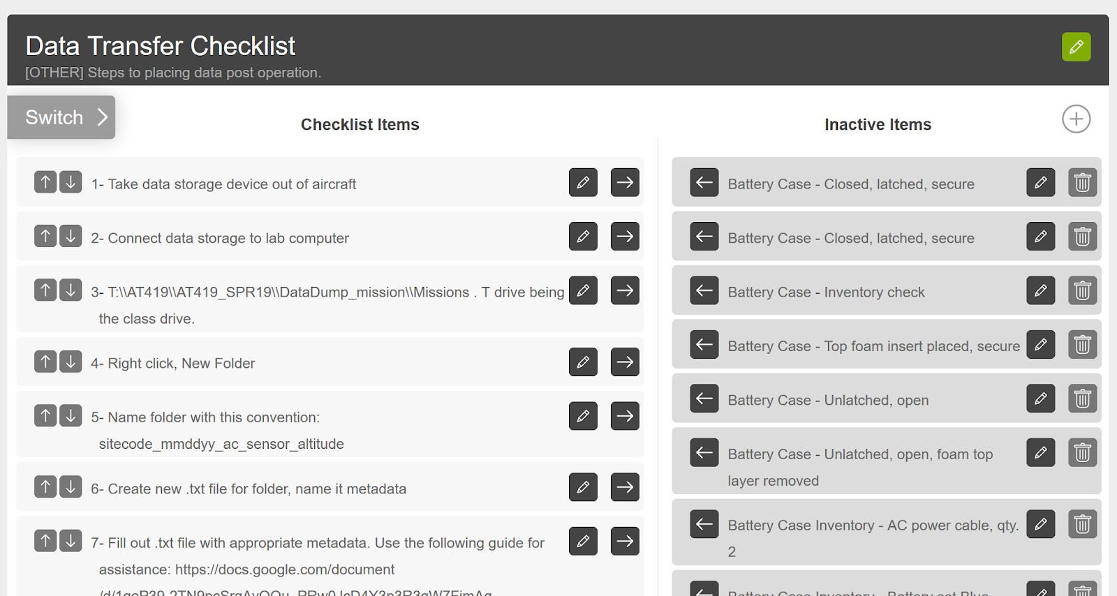
The primary and ongoing task of the week was to finish our final checklist before we can begin flight operations once the weather improves. This checklist is the data transfer checklist. Being far more descriptive than a traditional checklist, it is more like a step-by-step extended guide regarding how to properly transfer, save, and format data post-mission. Its purpose is to ensure that there can be a simple transition for data personnel to begin processing the data without confusion regarding where the data is, what the data is, and what should be done to it. In order to remain consistent with other checklists, the Drone Logbook interface was used to store the checklist.

Working with Drone Logbook exposes some of the issues with the technology. First of all, the checklist can only be accessed by either reading it directly from the website, or by starting a flight on a mobile device. This is not necessarily an issue as long as we train flight crews to not conclude the flight until data has been stored. The other issue is the functional style of Drone Logbook's checklist creation interface. Essentially, when someone creates a new checklist, they are just creating an empty bin where steps can be created or moved into. While you can create each step in the active checklist (left of figure 1), it also populates the list of steps that have been created for all checklists (right of figure 1). This not only creates a clunky confusing interface, but it presents functionality issues. If someone accidentally moves over a step from the list on the right, it can significantly alter the order of steps that were in the right location. Because the app does not have a drag-and-drop feature, the arrow buttons must be used to move checklist steps, which is very time consuming and has potential for errors. Another issue with this format is that if I wanted to move a step into the right list (figure 1) that effectively acts as storage, it would be incredibly difficult to find the exact same step because it would be populated somewhere among the massive list of steps containing every step from every checklist we have generated. Drone logbook needs to include a function to bin checklist items in some sort of folder structure that can be filtered out or the feature could become unusable in the long run. Drone operations are simply too complicated with too much variation between ground equipment, vehicles, and residual steps for the Drone Logbook approach to checklists.

Figure 1: Subset of Data Transfer Checklist on Drone Logbook. The left side is a correctly populated list of checklist items. The right is the non-filterable list of inactive items.    


SATT Poster Symposium 

An announcement for our school's poster symposium was made this week, and we decided that we would enter a series of posters. While the complete list of posters seems inconclusive at the moment, what seems certain  is I will be leading the poster regarding the specific type of application our capstone is centered on with Krysta. I will also be conducting preliminary data-analysis as part of the poster, in particular comparing accuracy of different methodologies, which will be useful throughout the rest of the project. Krysta and I will be comparing the accuracy of flood extent delineation between two different drone remote sensing methods. The first will be a manual geospatial video technique, and the second will be an autonomous multispectral photogrammetric approach.  Accuracy will be determined by comparing where flood water can be delineated in each method to ground control measurements taken at the extent of flood waters by ground crews. I suspect that the geospatial video technique will be less accurate, but be able to cover a larger area in far less time than the autonomous technique.

The basic methodology needs to be designed further, as well as various aspects of the poster itself. Most of this will happen next week (week of 2/18). Despite the lack of various details at the moment, I have generated a basic timeline that will be used to gauge progress and ensure all mandatory steps are completed (Figure 2).

Figure 2: Timeline for SATT Poster Creation.

This upcoming week will largely be structured around flushing out the details for the poster. Krysta and I will meet Wednesday to discuss what type of literature review she has completed, what we can take from that, and what additional details we will need. I assume that some additional literature will need to be collected regarding remote sensing of water, the need for flood analysis by air (by drone), and any other specific UAV studies that may have been conducted on this topic.

Saturday, February 9, 2019

Closing in on Functionality: Weeks of January 28th and February 4th

The past couple of weeks have been quite busy with residual non-project related tasks. This is actually why there was no individual post for last week, as I was out of the state interviewing for graduate school positions for multiple days. For that reason, instead of omitting a weekly post all together as I was allotted, I have decided to mix the two week posts into one. This is actually quite beneficial as both my tasks these two weeks are related.

Task 1: Plan a Hypothetical Scenario

The first task, which was been completed in entirety,  was to complete a hypothetical scenario for my classmates to run through while I was absent for interviews. We had been planning a gaming scenario to create, plan, hypothetically execute, and assess a mission so that it would be easy to discover where additional work needs to be conducted as we approach the field season. My job was to come up with an environmental condition that would be beneficial for us to address for our project.This step was important for two reasons. The first reason is so that we can determine if we have the equipment and processing capability to collect data on a short duration event that could occur at any time. The second reason is to see if group members could come up with the correct means of collecting the proper type of information for a given condition. This is a critical skill to train or at least determine how well we can perform because there may be situations during the field season where we would like to collect data of an environmental event that can not be scouted ahead of time and require field teams and flight crews to successfully determine last minute how to fly, where to fly, and with what equipment to fly and collect data. Being that I am the individual with the most data experience, there may be moments where I can not be present to help select which sensor to use and individuals in the field may need to make the executive decision. The hypothetical scenario I tried to build would gauge this ability.

The scenario I planned involved a sudden warm day after significant snowfall (not uncommon in Indiana). This warming event rapidly melts local snow and creates a very significant flooding condition in the Wabash River near our field site. In the scenario, flood conditions were expected to decrease rapidly in a very short amount of time (in a few days) as well as general velocity was expected to decrease. Giving the group this information, a few keep conclusions were expected to be made. First, flooding area should be assessed as well as height and velocity. The hope was that they would also determine that recurring flights over a few days would be useful to determine how accurate the flood forecasting is for the river and to help train/compare flood models we made decide to make later in the semester. For flood area analysis, I would accept any possible type of data collect that could successfully delineate the feature. Geospatial video would be a good option as a UAV could overfly the flood perimeter to help determine how much of our site is flooding. Multi-spectral imagery would also be useful as the spectral difference between water and ground is immense in the near-infrared band. While these two techniques are what I would chose, I would welcome other ideas as this might inform me on other possibilities for the rest of the semester. I did not have any intended aircraft for them to use as this is mostly a topic for other crew members, plus there could hypothetically be any number of options or combinations of aircraft that could help complete this task. Because I did not specify how much area would be covered by the flood, I do not have an expectation for which flight area they should try to cover as long as it is logical and includes the river. I was also hoping they would at least consider flight areas and launching from the opposite side of the river from Tippecanoe park as this area would certainly be flooding in this scenario (lower laying homogeneous landscape). After determining all this, materials prepared by other group members would be included and used in the appropriate point of the scenario to determine if more documentation or information is needed. I was absent when they ran the scenario, so this upcoming week I am sure I will hear of the results.

Task 2: Finish a Data Post-Flight Document

The second task during this time period is still in production as it is time intensive and I had limited availability. By the next weekly report, the expectation is that a data post-flight checklist or guide will be produced. This guide will explain various aspects of data group members will need to interact with that we have already discussed, as well as some new features.

The First step in the document will sound like a continuation of the equipment guides Ryan and Ian's group are producing. It will involve how to manipulate and download data from the SD cards of the aircraft post mission onto the computers. It will detail where to save data so I consistently find it and how to name the information so that I can understand where the data is coming from and its importance. The details of how this will work is in previous posts involving naming convention of files and folders.

The second step will details to creating a metadata file inside of the data folder they are to produce. The specifics of this have also been discussed previously and I have already generated a document that will contain a guide for what needs to be included and how it should be structured for metadata purposes. If this step is done correctly in accordance with previous steps, data should be able to simply be moved from public drives into the correct folder on the research drive and will be ready for processing and analysis.

The final steps of the guide will again sound like a checklist. These steps will first discuss how to properly reformat the SD cards so that data is properly wiped. The rest of the list will involve placing the SD cards back into the aircraft or sensor. Lastly, how to store the aircraft depending on its specific schedule (should it be flying very soon or after a few days). This guide will be the final of the checklists and should complete our capability to begin data collection missions. With any luck and a change in the weather, we should begin flying data collection missions soon.

Monday, January 28, 2019

Third Post

Week of 1/21/2019


File Pathing

This week, the focus shifted back towards file/folder pathing and demoing potential processing workflows. The folder path structure assigned is fairly simple, and just adds the appropriate folders to the research drive. The new folder structure takes a "broad to specific" approach. The first folder is a data folder for the course, than a specific folder for this semester, then a set of folders for any type of information needed to be saves such as data or flight area shape file assignment. Within the data folder, specificity increases with a folder for location codes (see week 2 post for explanation of location codes), with each location having its own folder. Within a location folder, a folder for GCPs exist as well as a data type folder. Within the data type folder, folders exist for each type of data we plan to collect such as geospatial video or multispectral imagery. Inside each of those folders, missions are saved as per the naming structure assigned in a previous blog post. Within the mission folders, a folder for images, processing, analysis, and final products exists.

While there is obviously many folders to click through in this structure, it should make it easier to find specific data sets. This is because one simply clicks on the information of the data they are searching for until they reach the final dataset.


Demo Dataset

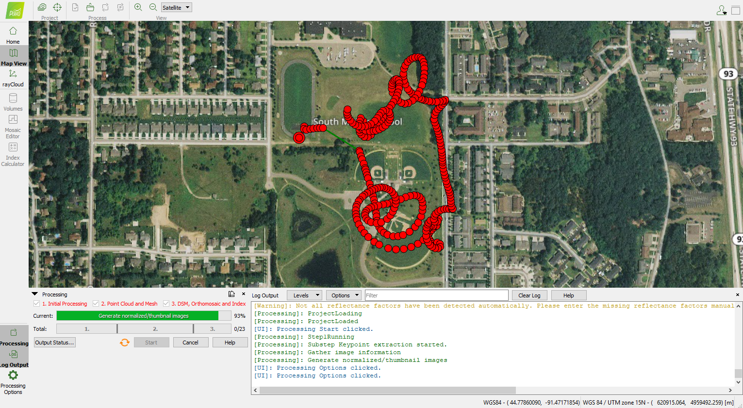
The second task of the week was to test Pix4D on the new lab computers. Photogrammetric workflows had yet to be tested on the new computers, so I ran a simple multispectral orthomosaic processing workflow in the program. The data set I used was collected during a launch and land test flight of the C-Astral Bramor fixed wing aircraft, so the data was not collected in a mapping mission. I chose this data set because it would mean some of the data collected would be of lower value, unlikely to properly rectify or rectify accurately. The test flight provided a heterogeneous set of data to interact with during processing and while inspecting products. The entire data processing workflow took approximately an hour and a half to complete on the weaker set of computers in the lab (32gb of RAM).  While there were areas of lesser quality in the final orthomosaic, DSM, and textured mesh, this was expected with the erratic flight path of the aircraft. There is no indication that Pix4D would not suffice as the processing software for this project on these computers.

Figure 1: Pix4D main processing screen


Figure 2: Orthomosaic with cameras transposed onto the imagery in 3D. Shows flight path of the aircraft

Figure 3: zoomed in image of the orthomosaic in the NIR band. Relatively strong mosaic data quality (straight roads) with only a few errors (dark area west of baseball diamond)